Icom Q7 S-meter mod
With only 2 extra components the range of
the S-meter can be extended from 10dB to 35dB.
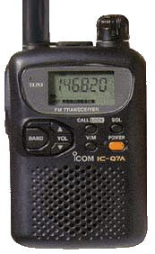
The Icom Q7 (Q7E or Q7A) is a small and handy transceiver. I am mainly
using it as a scanner, but it can also transmit on the 2m and 70cm.
If you got it from a good supplier, or if you modified it, you can also
transmit outside the amateur bands, which can be very convenient to test
things. Also it has a wide reception range, from 30MHz to 1.3 GHz (or
even more when tweaked with a piece of software). And 200 channels is
more than enough for most applications.
So it's got a lot of good characteristics, but I found a big point for
improvement: the S-meter.
The Q7's S-meter has a range of only 10 dB, which is far
to little to be useful. In practise, it will give full scale at any signal.
This problem could have been solved easily by the programmers of the
internal software. After some research I found out that they take the
RSSI voltage of the IF mixer, feed it to an A/D input of the controller,
digitize the value (8-bit), substract an offset (about 120), divide by 4,
and use the resulting value for the number of blocks for the S-meter
(a block being 1 or 2 units of the bar).
Well, they should have divided by a lot more, like 12 or 16. This would
give the meter a range of about 35dB, being much more usefull. This would
mean each block would be about 7dB.
Most 'professional' S-meters have 9 units of 6dB each, followed by a
couple of units for 'very strong signals'.
The Q7 will never make it this far. The signal has already been amplified
when it enters the TA31136, which does the IF mixing and has the RSSI
output. At a very small, just receivable signal the RSSI output gives 1.4V.
At a medium signal (a local repeater at 0.5 km) the output gives 2.1V.
The problem is that the S-meter of the Q7 already shows full scale at
1.65V. That means a large part of the RSSI voltage range can never be used.
Because the internal software cannot be altered easily, a hardware solution
is the only practical option. Fortunately all that is needed is a resistor
of 22k in series with a led (for the offset voltage) connected to the
RSSI output.
You should take care to take a led with a low voltage drop, 1.4 Volts at
a current of several tens of uA.
Just try a few (red) leds on your multimeter in Diode-measurement mode,
and find one with this voltage.
The schematic of the mod is this:
   ----------------------
     TA31136 internally  |
                         |
               + VCC     |
               |         |
             |/e         |
     - - ----|           |
             |\          |
               |    RSSI |12                   ____
               +---------------------+--------|____|---------------o to uP
               |         |           |         10k
              .-.        |          .-.        (against noise,
              | | 56k    |          | | 22k    can be removed)
              | |        |          | |
              '-'        |          '-'
               |         |           |
               |         |           |
              ===        |          ---
                         |          \ / led 1.4V
   ----------------------            v
                                    ===
                                     |
                                     |
                                    ===
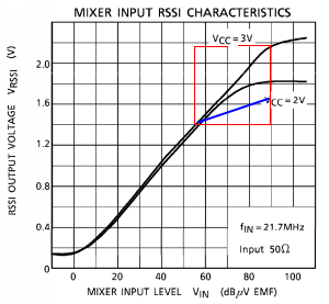 The RSSI output has an internal pull-down resistor of 56k, so
when the voltage is more than 1.4V, the incremental resistance is 3.5 times
as low as it was. That means that the 1.65 V is now reached at 3.5 times
higher signal levels, so the dynamic range of the S-meter is now also
3.5 times as big. The blue line in the graph at the right indicates the
new curve with the mod in place. You can see that the difference in input
level from 1.4V to 1.65V is now about 35dB.
The RSSI output has an internal pull-down resistor of 56k, so
when the voltage is more than 1.4V, the incremental resistance is 3.5 times
as low as it was. That means that the 1.65 V is now reached at 3.5 times
higher signal levels, so the dynamic range of the S-meter is now also
3.5 times as big. The blue line in the graph at the right indicates the
new curve with the mod in place. You can see that the difference in input
level from 1.4V to 1.65V is now about 35dB.
It seems that the mod does not influence the squelch setting in any way.
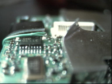
To apply this mod, you'll need to open the Q7 and unmount the 'back' print
of the Q7, which you see on top when you open the Q7. This involves
screwing and unsoldering. The unsoldering is on the following points:
a small point on the low side of the print, on the right side of the print,
and at the antenna connector (3 points). Be carefull not to touch any of
those small components. With the solder removed, the print should come loose.
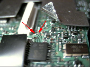
You don't need to remove any shielding metal for this mod. Bending the
metal a bit is sufficient, as you can see on the photos.
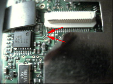
Once you have the back print in you hand, you should connect a small wire
to the RSSI output of the TA31136. The simplest place to do that is at the
wire going from the TA31136 to the white connector. There is a 10k resistor
in that line that, as far as I can tell from the schematic, only serves
to reduce noise from the CPU part.
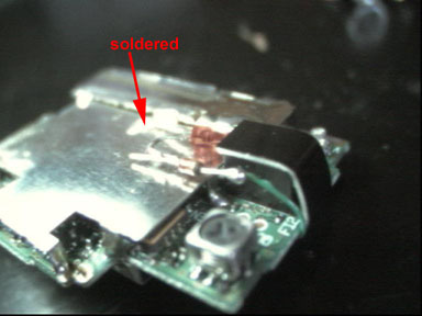
You should connect the wire to this resistor, on the side of the TA31136.
I accidently removed the resistor (being only about 0.4 mm in size),
and replaced it by a bridge of solder. It have not noticed any influence.
On the pictures the red arrows indicate where the resistor was.
To connect the wire you will need a soldering iron with a fine tip, that
should be no more than 300 degrees Celsius.
Once you have a wire connected to the RSSI output, you can turn the print
around carefully and connect the resistor of 22k and the led to it. The second
pin of the led can be connected to the shielding, which is ground.
Now bend back the shielding metal, put the Q7 back together again and enjoy
your improved S-meter.
Note: Although I hope this information is useful, I cannot be held
responsible for any damage caused by the use of this information.
|
Joris Robijn <joris(at)robijn.net>
|
last update: 2022-04-23 11:37:14 |
|
|